Design a PCB Board
- Estado: Closed
- Premio: €10
- Propuestas recibidas: 2
- Ganador: ranguerrero94

Resumen del concurso
Hello, we are Knowlize and we are working on a new project, but we need your help.
Please see hereunder the requirements of this work:
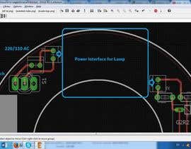
Project: Starting from our general sketch (attached file) create a fully working PCB board.
List of components:
- OSRAM LAMP GFT18DL/2G11/SE/OF 2G11
- VOSSLOH SCHWABE ELXS 124.902 1X14-24W TC-F-L, T5, T8, T-R5
- NOCTUA FAN 12V 0.07A
- FAN DRIVER
- 3 x LED 3020 SMD 3.4V 150mA
- STANDARD ON/OFF SWITCH
- LED DRIVER
- SAFETY ENDSTOP
- AC INPUT PINS
- LED OUTPUT PINS
- LAMP OUTPUT PIN (2G11 SOCKET)
- FAN OUTPUT PINS
Work description: By using the above component’s list create a single donut shaped PCB board (see the attached PDF for dimensions).
If you have any doubts, don't hesitate to contact us.
Good work
Update 06/07/2017
Uploaded some pics of the3 actual CFL lamp reactor. We hope it's enough since we do not have the schematics or the DXF.
Habilidades recomendadas
Tablero de aclaración pública
-

TokhirTR
- 6 años atrás
Hello. Can You help me? I head more information about LED DRIVER
- 6 años atrás
-

Organizador del concurso - 6 años atrás
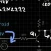
It could be something very simple liker this: https://www.google.it/search?q=led+circuit&tbm=isch&imgil=bzjQ-CCMUC3OYM%253A%253BPriffnvpNYzuoM%253Bhttp%25253A%25252F%25252Fwww.electroschematics.com%25252F2573%25252Fled-circuit%25252F&source=iu&pf=m&fir=bzjQ-CCMUC3OYM%253A%252CPriffnvpNYzuoM%252C_&usg=__O7gpoQbffIVy26Ad7QI367vjqSc%3D&biw=1280&bih=652&ved=0ahUKEwiF8dOo75PVAhVHUBQKHWzbCOoQyjcIMg&ei=QIpuWYXRN8egUey2o9AO#imgrc=bzjQ-CCMUC3OYM:
Don't mind the numbers, just to make you understand the workflow.
Input Current --> Resistors (or anything else needed) --> leds- 6 años atrás
-

jsinghvirdi
- 6 años atrás
Hello, i would work in your project, i would need all information about the board like what does it do and all kind of information you can provide to me.
i would design the circuit according your requirements like LED Driver design, 12V FAN power supply etc.
you can see some of my work in my profile- 6 años atrás
-
Organizador del concurso - 6 años atrás
The board shoun control 3 things::
1 - An UV-C lamp through the ballast (the ideal is to implement the ballast into the circuit)
2 - A 80 mm 12 V Fan
3 - 3 leds
The inputs are:
- AC 220/110 V
- A switchto start/stop the lamp/bulb/led
- A button to start/stop- 6 años atrás
-
Organizador del concurso - 6 años atrás
should*
- 6 años atrás
-

diegosoares90ml
- 6 años atrás
Sir, let me confirm some issues:
1) The ballast ELXS 124.902 will be implemented on pcb, just the circuit ok? And this item is exactly the photos you've attached?
2) Should I need to made exactly the same circuit, or can I project one with same functionalities?
3) In description you said: "3 x LED 3020 SMD 3.4V 150mA" and below "LED OUTPUT PINS". You are reffering the same leds? The leds are soldered direct on pcb, should it need an output connector?
4) Any connector are special? Or can I use simple terminals and you solder a wire?
Regards- 6 años atrás
-
Organizador del concurso - 6 años atrás
1) yes
2) you can do whatever you prefer
3)Yes, the output led pins are for the listed leds
4) simple terminals are great
thnaks a lot- 6 años atrás
-

ghufhas
- 6 años atrás
Kindly check my design and let me know if there is any mistake or ambiguity
- 6 años atrás
-
Organizador del concurso - 6 años atrás
Yes man, what is your design? the output pins config?
- 6 años atrás
-
ghufhas
- 6 años atrás
Sir actually I have mentioned output pin configs by labeling them but sir if you can kindly provide me circuit I can even more furnish it. I am using proteus for my design
- 6 años atrás
-

saifysyed
- 6 años atrás
#increaseprize.
- 6 años atrás
-
Organizador del concurso - 6 años atrás
this is only the beginning, if we found something with the right skills the work will be more and well payed.
- 6 años atrás
-
saifysyed
- 6 años atrás
increase it and you will definitely find one!
- 6 años atrás
-
Lal883
- 6 años atrás
1. Does the Ballast, VOSSLOH SCHWABE ELXS, need to be accommodated on PCB or just require mating connectors so that the ballast will be a separate module mounted else where?
2. List of components mention "LED OUTPUT PINS" and 3 number of 3020 SMD LEDS. Could you clarify if the LEDs will be on the Donut PCB or some where else?- 6 años atrás
Ver 2 mensajes más
-
Lal883
- 6 años atrás
Further clarification on (1). Since you have specified a model and type for ballast, I am guessing that the same module (as PCB) need to be mounted on Donut PCB. Or do you mean to replicate the circuit of specified ballast on to PCB? Wouldn't that second case be a kind of infringement.
- 6 años atrás
-
Organizador del concurso - 6 años atrás
Hi Lal883, it doesn't have to be the same circuit, it has to do the same thing, light up the 18W lamp
- 6 años atrás
-

urbito
- 6 años atrás
hello, i am sending you a proposal
- 6 años atrás
-

skilkhan
- 6 años atrás
Circuit Diagram?
- 6 años atrás
-
Organizador del concurso - 6 años atrás
That's the point the circuit Diagam..
- 6 años atrás
-
Organizador del concurso - 6 años atrás
Reply for everyone:
We do not have the circuit diagram, but We know what we want inside, well I know it's tricky but now We'll try to upload some pictures of the actual components- 6 años atrás
-

ranjithnaredla
- 6 años atrás
I am interested to do this project. I have created so many pcb's like this. I need your DXF file. This is suffiecient enough to me.
- 6 años atrás
-

roy91591
- 6 años atrás
sorry sir photo is no upload on this place
- 6 años atrás
-
roy91591
- 6 años atrás
sir your information is not
enough to complete your project,
, you need a PCB board but you
dont give us the main designe
(your project circut) like this photo,,,
how can i designe your pcb board.- 6 años atrás
Cómo comenzar con los concursos
-

Publica tu concurso Fácil y rápido
-

Consigue toneladas de propuestas De todo el mundo
-

Elige la mejor propuesta ¡Descarga fácilmente los archivos!